


How a Slip Ring Works?
Problem:How can I get electricity to a continuously rotating part of my assembly?
For example, if I want power available in a tank turret, how can I enable the turret to rotate without limits?
Solution:
Use a sliding contact slip ring!
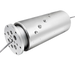
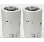
Slip rings enable the transfer of electric power or signal circuits across a rotating surface, such as those found in radar antennae, gun turrets, periscopes, electro-optic sensor gimbals and space satellites. The sliding contact is established by a brush that presses against a metal ring. The “brush” can look like a brush made from metal fibers, but more often it looks like a single wire or a spring with a pad of material affixed to the end that contacts the ring. Figure 1 below shows a brush block for a four pass slip ring. Each ring on this design has two brushes. In this unit brushes for two of the rings have a yellow plastic shield to isolate high voltage circuits. Next to the brushes you can see a cylindrical drum with four silver rings. Figure 2 shows these two components arranged as they would be inside the housing of the slip ring so that the pads at the end of each brush are pressed against the rings. Wires lead from the brushes and from the rings, and these are used to connect the electrical circuits. You can see that the cylinder holding the rings is free to rotate while the brushes press against the rings. In this design each ring has a single brush with two contacts.
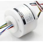
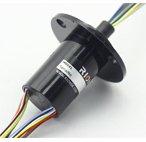
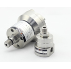
Housings provide a framework to keep these components in relative position. Figure 3 shows an assembled slip ring with the cover removed. You can see the drum (properly called a rotor assembly) with the tips of brushes pressing against them. The housing can be designed to protect the working parts from dust and moisture. Bearings are usually employed at both ends of the drum to provide structural stability and easy rotation. Customers often require connectors on the lead wires to enable them to install the slip ring into their systems.

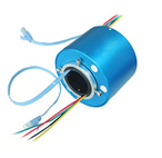
Slip rings can be designed in a variety of configurations. For example they can provide an open through-bore to accommodate other components such as a fluid joint or a wave guide. Instead of a drum the rings can be configured in a platter or pancake. This is appropriate if the space available for the slip ring is short and wide instead of tall and narrow.
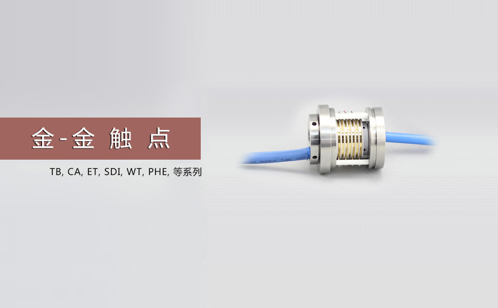
A critical aspect of slip ring design is the materials used to make the rings and the brushes. After World War II manufacturers responded to requirements from the emerging electronics industry with gold plated rings using gold wire brushes. Up until the 1970’s many slip rings used copper rings and graphite brushes. Copper is smooth and conducts electricity well. Graphite conducts well, it is soft, and it does not abrade the copper rings. But for advanced applications such as space satellites and missiles, graphite brushes were inadequate. There was a burst of research and invention in the early years of the space program to address emerging needs, mostly in space and missile programs, that produced advanced gold on gold alloy systems and systems that employed silver alloy rings with brush tips made from silver graphite mixtures. Today these two systems, gold-on-gold and silver/silver-graphite, are the mainstays of the slip ring industry. Gold-on-gold systems are often used for low current signal circuits because they are compact. Silver/Silver-graphite systems are often selected for higher current power circuits because in these applications they are more economical, and have long service life.
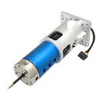
Today’s slip rings are reliable, have long service life and can be designed for extraordinary environments, including the vacuum of space, the shock of a tank gun turret or the vibration of a helicopter rotor. For guidance on how to specify a slip ring